To match with the pin assignments of a port header, wires can be shifted
and repositioned within the connector. In some cases, you need to change the
connector to suit the layout of the header.

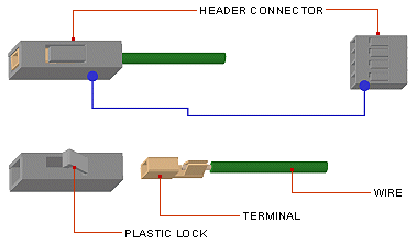
Diagram 1: Use the tip of a blade and slide it in from the side of the
plastic lock.

Diagram 2: Move in the blade horizontally at the bottom of the plastic
lock to release the lock from the terminal. Then, pull out the wire.

Diagram 3: Insert the wires back into the connector at appropriate
positions to match with the pin assignments of the motherboard header.

Diagram 4: With the same method as above, you can change the connector
if necessary. Varios types of header connector can be purchased at our
webstore.
UNIVERSAL STANDARDS

All motherboard headers (pinouts) follow the same universal standards
in terms of pin size and pin spacing (i.e. pitch 0.1" / 2.54mm), and
similarly, the same universal standards apply to the design of all header
connectors.

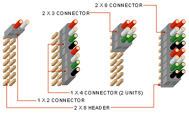
Since the size and spacing of the pins have been standardized, different
versions of connector can be plugged onto the pinouts with great flexibility.
Refer to the illustration above, it reminds you of the "Lego" assembly. Note
how 1x2, 1x4, 2x3 and 2x8 connectors can be plugged onto the same 2x8 pins
header at so many different ways.
RELEASE-ABLE WIRE ASSEMBLY
The best feature of the header connector is its release-able wire assemby.
Wire is crimped to a female terminal which can be inserted into the
connector's slot and is self-secured by a plastic lock. Similarly, the wire
can be easily released from the connector by raising the plastic lock.
